Steel Buildings for Sawmills and Timber Processing
Discuss Your Sawmill Building Requirements
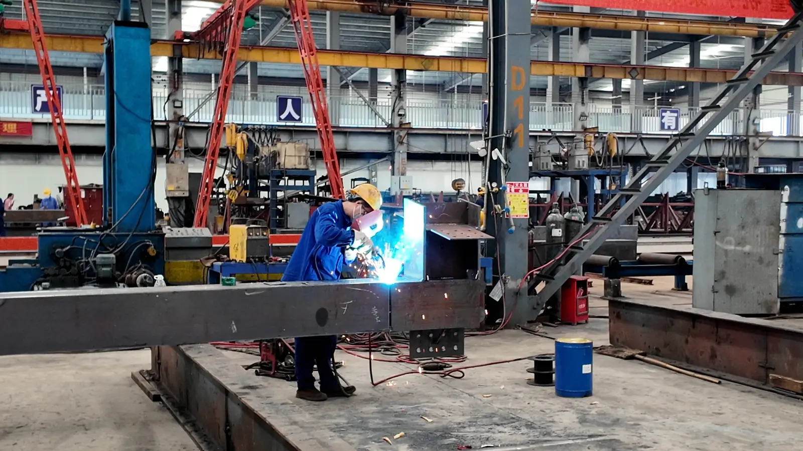
Bingfa fabrication reference. General steel welding, not a sawmill project.
A sawmill building must accommodate the movement of long material as well as the machinery inside it. Log infeed, sawing, sorting, stacking and dispatch can impose different requirements on columns, openings and covered space. Planning the steel shell before these routes are understood can leave a workable production line with an awkward building around it.
Bingfa can discuss project-specific steel fabrication and agreed roof and wall enclosure supply for timber-processing facilities. The building scope must be coordinated with information from the buyer, equipment supplier and responsible engineers. Sawmill machinery, production-line design and specialist process systems are not included by default.
Start with the Timber Flow, Not a Standard Shed Size
Describe what enters the site, what happens inside each building and what leaves for storage or dispatch. A mill handling logs has different interfaces from a workshop processing already-sawn timber. Product length, handling equipment, storage method and the sequence of operations should be clear before a building layout is treated as fixed.
Prepare a simple route drawing connecting the outdoor yard to the covered work areas. Show the normal material path, rejected or diverted material, chips and offcuts, maintenance access and vehicle movements. The process supplier should confirm the actual sequence; receiving, sawing, sorting, stacking and dispatch are planning categories, not a prescribed production line.
For broader building coordination, see our industrial steel factory building page. The additional focus here is long-stock movement and the interfaces between timber-handling equipment, covered processing areas and the yard.
Map Each Process Zone to a Building Interface
| Zone | Process Input | Building Interface | Confirmation Owner |
|---|---|---|---|
| Log receiving and infeed | Stock lengths, unloading method and infeed equipment outline. | Yard approach, entry opening, roof edge and collision clearances. | Buyer, process supplier and site designer. |
| Sawing or machining | Equipment footprint, operating envelope, services and maintenance access. | Column and bracing positions, usable height and approved openings. | Equipment supplier and responsible structural engineer. |
| Transfer and sorting | Conveyor routes, turning or transfer space and product discharge points. | Uninterrupted routes through bays and enclosure interfaces. | Process supplier with the building design team. |
| Stacking and storage | Bundle sizes, handling method, storage conditions and access aisles. | Covered area, access openings and confirmed structural interfaces. | Buyer, handling supplier and civil designer. |
| Dispatch | Vehicle dimensions, loading method and staging requirements. | Door locations, covered loading boundary and yard connection. | Buyer and logistics/site planning team. |
| Chips, offcuts and dust | Separate collection and removal routes, specialist system information. | Penetrations, supports and external equipment locations. | Process and extraction specialists, coordinated with building engineers. |
Check the route as a whole. A clear opening at one machine does not prove that the next transfer point, bracing bay or yard exit is usable. Separate pedestrian routes from material-handling movements through the project safety and operational planning process.
Choose Span, Clear Height and Columns Around the Equipment
Identify where the process genuinely needs an unobstructed bay and where intermediate columns may be acceptable. Review the full movement envelope of long stock, not only the machine footprint. Include loading, discharge, turning, maintenance and replacement access before agreeing on the grid.
Clear height should be measured to the lowest relevant obstruction along the required route. Roof framing, bracing and services may affect the usable space. There is no universal sawmill span, column spacing or clear height suitable for every line. Dimensions must follow confirmed operational inputs and project-specific structural review.
Large equipment may need an installation opening different from its everyday operating access. Agree whether that opening remains permanent or needs a planned closure detail. Our equipment installation route checklist can support that discussion without replacing the equipment supplier’s lifting and installation plan.
Keep Machine Loads and Building Loads Clearly Assigned
The equipment supplier should provide the technical information needed by the responsible designers, including relevant support locations and actions, operating effects and service requirements. A machine’s shipping weight alone is not a complete basis for designing its supports or foundations.
Confirm whether equipment is supported by independent foundations, the floor system or specifically designed steelwork. Identify who prepares the calculations, who approves the interface drawings and who communicates later changes. Machine vibration, moving loads and equipment alignment requirements need project-specific assessment.
Crane systems, machinery-support platforms and tall process structures are not assumed parts of a standard building package. Where requested, their feasibility and scope require separate technical confirmation. Likewise, the steel building supplier’s reaction information does not replace geotechnical investigation or the responsible civil engineer’s foundation design.
Coordinate Weather Protection and Specialist Process Areas
Some operations may combine open-sided covered areas with enclosed processing or storage spaces. Discuss wind-driven rain, local wind conditions, drainage, exposure and the intended storage environment. An open side is a design input, not permission to remove planned cladding or bracing after fabrication.
Moisture and condensation requirements should reflect the timber condition, climate and use of each zone. Insulated enclosure options, where required, need a defined performance basis rather than an assumption that all timber storage must be enclosed in the same way.
Drying kilns, treatment areas and chemical processes may create different temperature, moisture or corrosion conditions. Keep these as explicit specialist interfaces. The building quotation should state what surrounds or supports them and what is supplied by others; it should not imply that an ordinary steel shell includes kiln equipment or treatment-system engineering.
Leave Dust, Fire and Extraction Design to the Responsible Specialists
Wood dust requires deliberate control. General building ventilation should not be presented as a substitute for suitably designed extraction at the machinery. HSE woodworking guidance identifies machine and layout information as inputs to extraction design. It is a professional reference from the UK, not a statement that one set of national requirements applies to every export project.
Fire and explosion assessment, extraction systems, discharge locations, noise control and occupational safety should be assigned to competent specialists under the applicable local requirements. HSE also identifies fire and explosion risks associated with wood dust. This page does not specify a safety system or guarantee regulatory approval.
Once the specialists provide approved inputs, coordinate roof and wall penetrations, equipment supports and maintenance access with the steel and enclosure drawings. Use the service penetration coordination guide to organize these interfaces, not to size an extraction or fire-protection system.
Agree on the Supply Responsibility Matrix
| Work Package | Scope to Define | Required Interface or Exclusion |
|---|---|---|
| Primary and secondary steel | Agreed fabricated members and connection supply. | Approved drawings, design responsibility and equipment-related loads. |
| Roof, walls and openings | Agreed enclosure materials and accessory schedule. | Weather, process and specialist opening requirements. |
| Saws, conveyors and sorting equipment | Equipment supplier’s package. | Not default Bingfa supply; provide layouts, clearances and interfaces. |
| Extraction and fire systems | Specialist design, equipment and approvals. | Not default building supply; coordinate supports and penetrations. |
| Machine foundations, slabs and civil works | Responsible civil designer and contractor’s scope. | Site information and confirmed structural/equipment inputs. |
| Yard, drainage and vehicle areas | Site planning and civil construction package. | Connect floor levels, entrances and external operating routes. |
| Installation and lifting | Appointed contractor’s work and agreed supplier assistance. | State included services, exclusions and erection responsibilities explicitly. |
A quotation should identify each included package and its exclusions. Describing a complete operating facility does not mean that one supplier is responsible for every process, civil work or installation activity.
Prepare Information in Three Stages
| Stage | Buyer and Specialist Inputs | Decision to Record |
|---|---|---|
| Initial RFQ | Location, intended use, approximate dimensions, process outline, stock sizes, yard sketch and available drawings. | Quotation assumptions, preliminary scope and missing information. |
| Design coordination | Equipment layouts, operating envelopes, loads, site/design conditions and specialist requirements. | Responsible designers, agreed interfaces and unresolved items. |
| Fabrication release | Reviewed drawing issues, openings, supports, enclosure schedule and supply boundaries. | Approval status and treatment of subsequent changes. |
Complete construction drawings are not required for an initial discussion. However, preliminary information should remain clearly identified, and affected interfaces should be resolved before the corresponding manufacturing release.
Bingfa Steel Fabrication and Export Preparation
Bingfa is a steel structure manufacturer in Guangdong, China. Its established manufacturing activities include cutting, fabrication, component identification and packing. Buyers can review our fabrication capabilities and discuss the steel structure and enclosure scope needed for their project.
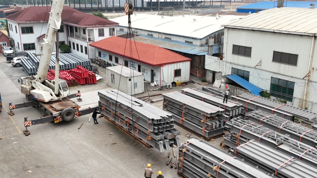
This page is an application-planning solution, not a claim that Bingfa has completed a documented sawmill project. The photographs show general Bingfa manufacturing and packing. Equipment performance, complete production-line delivery, specialist systems and overseas installation are not included unless separately confirmed within an agreed scope.
Frequently Asked Questions
Can the building layout follow an existing sawmill equipment plan?
The available plan can be reviewed as an input. The equipment supplier and responsible engineers must confirm operating envelopes, loads, openings and interfaces before the building drawings are finalized.
Does the building quotation include saws, conveyors or drying equipment?
Not by default. The quotation should distinguish the steel and enclosure supply from machinery, process systems, foundations and installation supplied by others.
Is an open-sided building sufficient for dust control?
Do not assume so. A competent specialist should assess the actual machinery and dust risks and define the required controls. Building ventilation and specialist extraction are different responsibilities.
What should buyers send before requesting a price?
Send the location, process description, approximate building dimensions, stock and handling requirements, available layout and intended delivery scope. Identify uncertain equipment or specialist requirements so they remain visible in the quotation assumptions.