Steel Buildings for Precast Concrete Plants
A steel-framed production hall for a precast concrete plant must be coordinated around the casting beds, mould areas, curing zones, lifting equipment and transfer routes that define the production process.
Discuss Your Precast Plant Building Requirements
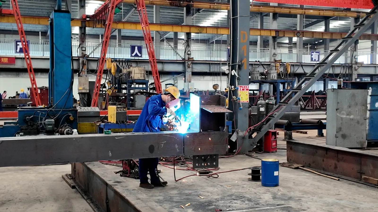
Bingfa fabrication reference. This photograph shows general steel welding, not a precast concrete plant project.
Bingfa supplies steel building structures and fabrication; the building brief should be developed together with the buyer’s process and equipment information, with supply responsibilities confirmed in the written quotation. The building frame is steel, which is different from a building made from precast concrete products.
Start with the Precast Production Layout
The first step is to understand what concrete products the plant will produce and how the production process is expected to operate. The production layout, equipment selection and concrete mix design are established by the buyer’s process team and equipment suppliers. The building brief should receive that information and coordinate the steel structure around it.
Buyers should distinguish between initial planning information and approved information required before fabrication. A preliminary layout, sketch or description of the intended production flow can support an initial discussion. Approved information — such as final equipment envelopes, crane data and agreed foundation interfaces — is required before a final structural proposal and fabrication release.
Coordinate Casting Beds, Mould Areas and Transfer Routes
Fixed casting beds, mould tables, reinforcement preparation areas, curing zones and transfer equipment can constrain column positions, bracing locations and access openings. There are no standard bed lengths, production capacities or universal column grids that apply to every precast plant. These dimensions must come from the buyer’s process and equipment information.
An illustrative coordination route can help identify the building interfaces:
casting position → demoulding/lifting position → temporary staging → building exit or crane-served exterior zone → storage/dispatch yard.
This is an illustrative route, not a layout for every precast process. The buyer and equipment team should identify the bed/mould envelope, end access, working and maintenance space, and movement envelope. These items identify areas where a column, brace or doorway must be checked for conflict. Request dimensions from the responsible team; do not assume standard bed lengths, access widths or column spacing.
Prestressing arrangements, if relevant to the buyer’s process, remain specialist equipment and civil engineering scope. Do not assume all precast processes use prestressing, and do not assume a building frame can absorb bed forces without explicit design review.
Coordinate Clear Span, Column Grid and Usable Clear Height
Clear span, column grid and usable clear height are three related but distinct building-interface decisions. They should be reviewed against the casting-bed layout, mould and transfer routes, crane coverage, enclosure, foundation interfaces and the confirmed equipment data provided by the process team.
A clear-span arrangement may reduce internal obstructions, while a multi-span arrangement may be suitable where internal columns can be coordinated with the process. The appropriate column grid depends on the production layout, equipment access, roof system, crane path, bracing and foundation interfaces. There is no universal grid or span that applies to every precast plant.
Eaves height is a building geometry reference. It is not the same as usable clear height inside the hall. Usable clear height is affected by roof framing, bracing, suspended services, crane components and the space required above the equipment. Hook datum, lifting attachments, component envelope and building obstructions must be checked together by the appropriate specialists. Do not apply a universal eaves-height formula.
Match Crane Coverage to the Building Interface
Crane coverage is often a critical interface in a precast production hall. The building brief should request the crane supplier’s drawings, the working envelope, lifting zones, required hook level and coverage. The requested inputs should include supplier-issued crane geometry, wheel and reaction data, relevant horizontal actions, duty or use information, and operating scenarios where several cranes interact.
Rated lifting capacity alone cannot define the building support arrangement. The crane supplier provides equipment geometry and actions; the appointed structural engineer uses the confirmed inputs for the building calculations. The buyer and equipment team should state the intended operating scenarios for that engineer to review.
First confirm whether crane travel remains entirely inside the hall or crosses the building enclosure boundary. These are different design scenarios; a crane crossing that boundary requires the coordinated runway, structure, enclosure opening and outdoor interfaces described below.
Clarify responsibility for each crane-related interface separately:
- Crane equipment — machinery, hoist and controls.
- Runway beams — building support steel and runway beams.
- Rails, fixings and end stops — rail system and accessories.
- Structural reactions — vertical and horizontal actions supplied by the crane supplier.
- Installation and alignment — who installs and aligns the crane and runway.
- Foundations and supporting structures — who designs and constructs the crane and building foundations.
Each item should be recorded as included, by others, or to confirm in the actual quotation.
General crane coordination is covered in the steel workshop with overhead crane page. Where multiple crane systems are discussed, refer to the industrial building with multiple overhead cranes page.
Separate Building Steelwork from Equipment Foundations
A clear responsibility boundary is essential. Casting beds, prestressing beds, moulds, machinery, lifting equipment, floor slabs and their foundations require the relevant specialist design and an agreed project scope. Their forces should not be assumed to transfer to the building frame without explicit engineering review. Any structural connection between the building and the production equipment must be confirmed by the responsible engineers.
The handoff should identify which team supplies equipment and bed loads, which engineer designs the equipment and building foundations, and who checks any proposed shared interface. Machinery, prestressing and curing systems, specialist equipment foundations, MEP and civil works require separate responsible-party scope and are not assumed to be included in a steel-building quotation. The building supply scope should be confirmed in writing, separate from the equipment and foundation scope.
Plan Enclosure, Curing Conditions and Yard Connections
The enclosure should be planned around the buyer’s process environment, moisture and condensation exposure, required openings, and the route to external storage or loading areas. Where curing equipment or special environmental conditions are proposed, the equipment supplier’s requirements should be provided and reviewed.
The yard connection depends on the actual transfer method:
- Transfer through an opening by transport equipment — request the loaded movement envelope, access route and opening dimensions.
- Overhead crane travel or loading across the enclosure boundary — request the agreed crane travel and coverage, runway transition, opening envelope, and the responsible structural, equipment and enclosure parties.
Do not assume every plant requires exterior crane runways, and do not assume a large door alone resolves the interface. Relevant outdoor equipment conditions require specialist confirmation. Steam systems, drainage treatment and humidity control remain part of the process and MEP scope. The building interface should focus on openings, enclosure, structural support and the transition to the yard.
Define the Steel Building Supply Scope
The following scope matrix identifies typical package elements and the corresponding buyer input and confirmation items. Not every item is automatically included. The actual scope is confirmed in the written quotation.
Table 1: Steel Building Scope Matrix
| Proposed building package | Buyer / equipment-team input | Scope to confirm |
|---|---|---|
| Primary steel frame | Building dimensions, column grid, load requirements | Included scope, design basis, interface with equipment |
| Secondary steel | Purlin/girt layout, openings, enclosure requirements | Included members, spacing, connection details |
| Crane-support interfaces | Crane supplier drawings, reactions, hook height, working envelope | Building support steel and runway beams to be confirmed separately from rails, fixings, end stops, crane machinery, controls and installation/alignment responsibility |
| Roof and wall enclosure | Enclosure specification, insulation, openings | Included panel/enclosure scope, accessory responsibility |
| Component identification and packing | Packing requirements, destination, marking system | Included marking, packing and loading preparation |
| Crane machines and controls | Crane supplier scope | Separate specialist supply unless included in the written quotation |
| Precast machinery, moulds and beds | Equipment supplier scope | Separate specialist scope and supply |
| Floor slabs and foundations | Civil/structural engineer scope | Separate specialist design and construction |
| Local civil works, MEP and process systems | Project team scope | Separate responsible-party scope unless included in the written quotation |
| Permits and local approvals | Local authority and project team | Not assumed included in the steel-building quotation |
| International logistics and site erection | Buyer/logistics and erection team | Delivery term and local responsibilities confirmed in quotation |
Review Your Production Hall Layout
Send your preliminary production layout, equipment information and building requirements for review.
Information for a Precast Plant Building Quotation
The following input table helps organise the information needed for a project-specific quotation. An initial discussion can start with a sketch and known requirements; unresolved technical inputs must be confirmed before final structural proposal and fabrication release.
Table 2: Project Inputs for a Precast Plant Building Quotation
| Input | What the buyer can provide | Building interface to review |
|---|---|---|
| Project location and design basis | Country, city, applicable code/design basis, issuing party and revision where available | Load inputs, local requirements, documentation |
| Concrete products and process overview | Product types, production method, flow outline, issuing party | Building geometry, access, internal zones |
| Preliminary equipment and bed layout | Sketch or layout of casting beds, moulds, curing areas, drawing revision | Column grid, openings, bracing, transfer routes |
| Equipment envelopes and supplier reactions | Dimensions, weights, support points, foundation loads, supplier-issued data | Floor/slab interfaces, structural support, clearances |
| Crane supplier information | Crane drawings, hook height, reactions, working envelope, issuing party and revision | Crane-support steel, runway interfaces, clearance |
| Internal and yard transfer routes | Route from production to yard/dispatch, loaded movement envelope | Door/opening sizes, aisle widths, enclosure transitions |
| Requested enclosure and curing-zone conditions | Moisture, temperature, ventilation requirements, equipment supplier data | Enclosure specification, openings, condensation interfaces |
| Agreed structural/support interfaces | Interface loads, connection requirements, responsible engineer | Structural coordination, connection review |
| Expansion assumptions if relevant | Future production or building expansion | Structural grid, expansion joint, site planning |
| Fabrication/enclosure scope and destination | Required supply scope, delivery destination | Quotation scope, packing, delivery term |
For buyers with confirmed production drawings, the structural steel fabrication from drawings page explains drawing-led fabrication scope. General factory building context is available at industrial steel factory building. Manufacturing and export supply evidence is described on the services page, and the broader solutions hub provides related application pages.
Table 3: Staged Information Handoff
| Stage | Information to provide | Responsible parties |
|---|---|---|
| Initial planning | Known location and design basis, process sketch, provisional bed/equipment layout, intended lifting route and supply scope. Record assumptions and missing data. | Buyer, process team, equipment supplier, Bingfa for building scope review |
| Structural design inputs | Coordinated layout, crane data, datum and clearances, equipment and foundation interfaces, responsible parties. Record current revision and unresolved matters. | Equipment and crane suppliers issue technical data; the appointed structural engineer prepares building calculations; the responsible civil or specialist engineer designs foundations. The buyer coordinates interface approval. |
| Fabrication drawing confirmation | Approved drawings and specifications, resolved relevant interfaces, authorized through the project’s actual approval process. | The buyer and authorized project engineer confirm drawings and interfaces under the agreed approval process; Bingfa releases the agreed steelwork for fabrication against that confirmation. |
This is an illustrative procurement sequence. An initial inquiry can start with available information; complete construction drawings are not required for that first discussion.
Manufacturing and Export Supply Evidence
Bingfa’s confirmed manufacturing processes include steel fabrication, component identification, quality checks, packing and export preparation. General steel fabrication relates to the agreed members and approved fabrication drawings. Identification and packing information helps compare received members with the agreed shipment documentation. Order-specific quality records, where agreed and available, relate to the documented scope, not automatic acceptance of a complete precast plant.
Real factory imagery and the existing factory video support these general manufacturing capabilities. The factory photograph on this page shows general steel fabrication, not a completed precast concrete plant.
Frequently Asked Questions
Can a production-equipment layout be used to develop the steel-building brief?
Yes, it can be used as an initial planning input. The layout, equipment envelopes and crane data help coordinate the building geometry. Approved equipment information and confirmed reactions are required before final structural proposal and fabrication release.
Are cranes, casting equipment and prestressing beds included in the building quotation?
These items are separate from the steel building supply scope for this proposal. Crane machines, casting equipment, moulds and prestressing beds require specialist design and supply. The steel building scope covers the building structure and agreed enclosure, with interfaces coordinated around the confirmed equipment data.
Can preliminary review start before all plant drawings are complete?
Yes. An initial discussion can begin with a sketch and the available process information. Unresolved technical inputs must be confirmed before the final structural proposal and fabrication release. Contacting Bingfa does not require complete construction drawings.
Can a generic warehouse shell be assumed suitable for a precast production line?
A generic warehouse shell may not address the specific casting-bed, crane and transfer interfaces of a precast production line. The building should be coordinated around the confirmed production layout and equipment data. Each project requires its own review and scope confirmation.
Request a Precast Production Hall Quotation
Send your project location, production overview, preliminary equipment layout, crane data if available, enclosure requirements and destination for a project-specific review.