
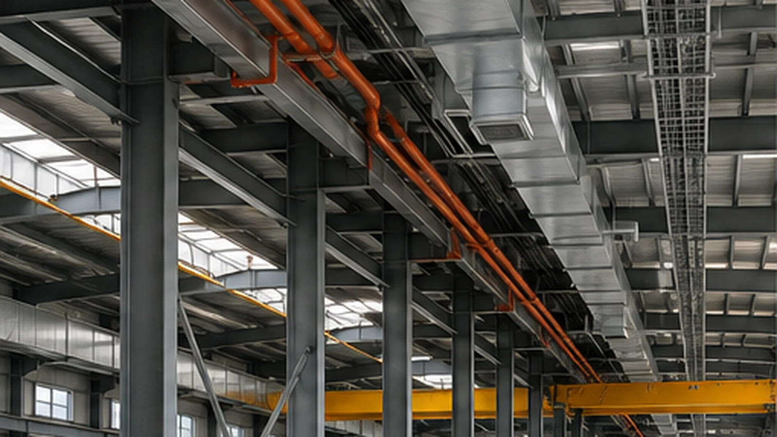
STEEL BUILDING COORDINATION GUIDE
Steel Building Service Penetrations: Plan Ducts, Pipes & Cable Routes Before Fabrication
Plan ducts, pipes, cable routes, ventilation and other service openings around structural framing, bracing and enclosure interfaces before fabrication.
Quick Answer
Service penetrations should not be treated as holes added after the steel building has already been finalized. Where known, openings for ducts, pipes, cable routes, ventilation, equipment services and other building utilities should be coordinated with structural framing, secondary steel, bracing, roof and wall panels, flashings and trims, drainage, maintenance access and equipment locations before fabrication and enclosure details are finalized. Detailed MEP, electrical, piping, HVAC, fire and process-system engineering should be provided by the relevant project specialists. Bingfa may coordinate steel-building openings and structural and enclosure interfaces based on confirmed project information.
What Are Service Penetrations in a Steel Building?
Service penetrations are openings or interface locations in the building envelope and coordinated framing zones that allow utilities and building services to pass through or connect with the building. These may include ventilation ducts, exhaust ducts, process piping, utility piping, compressed-air lines, cable trays, electrical conduits, equipment connections, roof-mounted equipment interfaces and wall-mounted equipment interfaces.
Not all service routes need to pass directly through primary structural members. The specific routing should be confirmed by the relevant project specialists. The building structure should be reviewed for known service openings before fabrication.
Why Service Openings Should Be Identified Before Steel Fabrication
Service openings that are introduced late in the project may affect structural framing, secondary steel, bracing, panels, flashings, equipment location and installation coordination. Identifying service penetrations early allows the building layout to be reviewed for potential conflicts before fabrication begins. Late changes may require additional coordination and may affect fabrication or enclosure details, depending on the timing and scope of the change.
Start With the Utility and Equipment Information
Buyers and project specialists may provide service type, approximate route, opening location, opening dimensions where known, equipment location, support requirements where relevant, maintenance requirements, available MEP and equipment drawings, and future service expectations.
Complete MEP drawings are not mandatory for the first steel-building inquiry. However, known interfaces should be provided early enough to inform the structural and enclosure coordination. The more information available, the more accurately the building can be planned around the required service routes.
For production-focused projects, the industrial steel factory building solution explains the broader relationship between equipment, utilities and the building layout. Where large equipment must pass through the structure, equipment installation route planning should be reviewed separately.
Coordinate Service Openings With Structural Framing
Service penetrations and openings should be reviewed against columns, rafters, beams, purlins, girts, bracing and secondary steel. It should not be assumed that openings can be cut on site after fabrication without engineering review. Any opening or modification that affects a structural member requires engineering evaluation.
Openings in non-structural panels may be easier to coordinate than openings in primary structural members. However, all penetrations should be identified before fabrication where practical. This page does not provide guidance on cutting, drilling or modifying structural steel members.
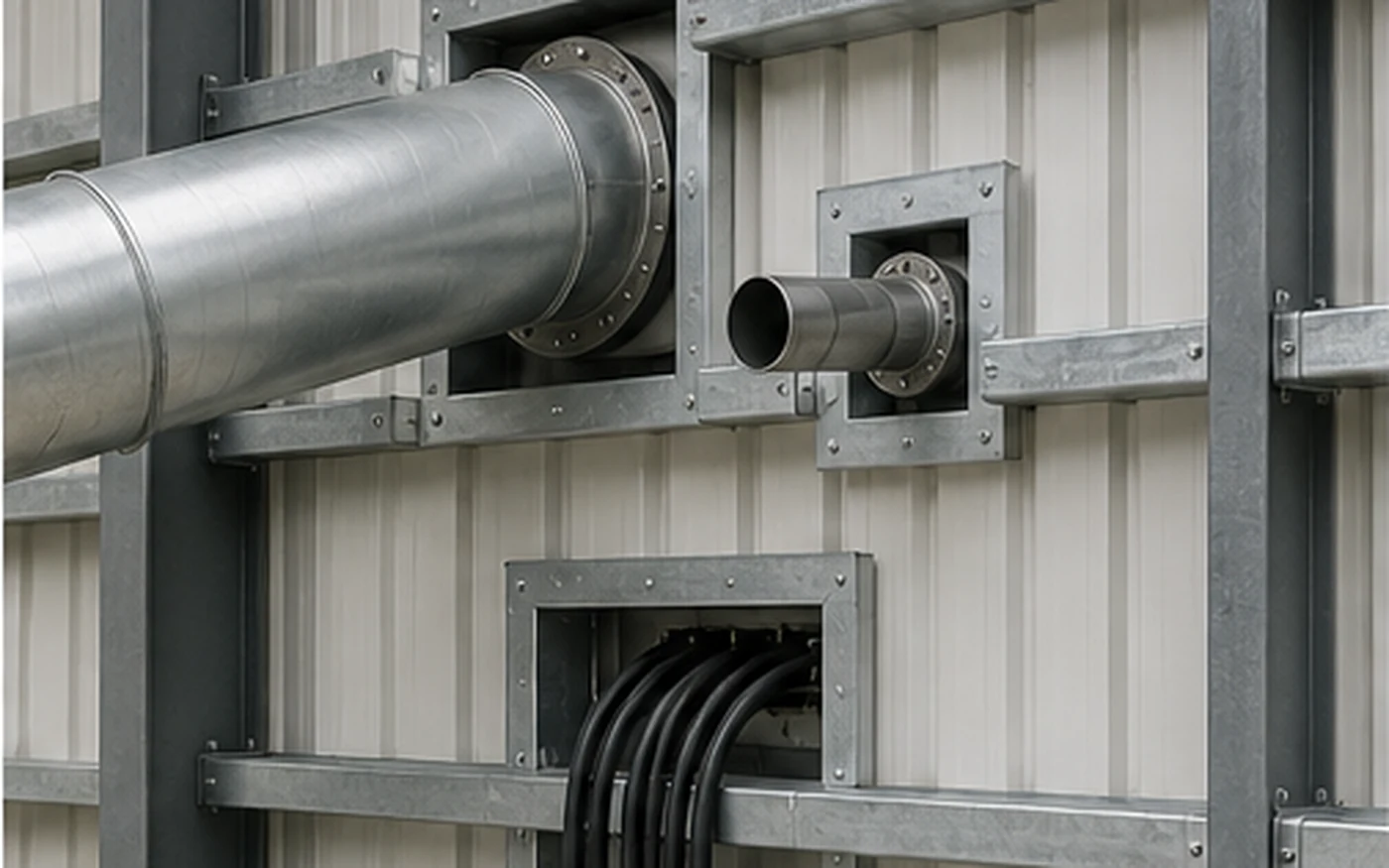
Wall Penetrations and Framed Openings
Wall penetrations may involve ducts, pipes, cable routes, louvers, service connections and equipment openings. These should be coordinated with wall panels, girts, secondary framing, trims and flashings, and weather interfaces. Related panel-specific interfaces are discussed in the guide to data center sandwich wall panels.
Wall openings are not the same as building doors. Doors are access points for people, vehicles and equipment. Service penetrations are utility openings that should be sized for the specific service routing. The type, size and location of wall penetrations should be confirmed before fabrication. Access-opening dimensions are covered separately in the steel warehouse door size guide.
Roof Penetrations and Equipment Curbs
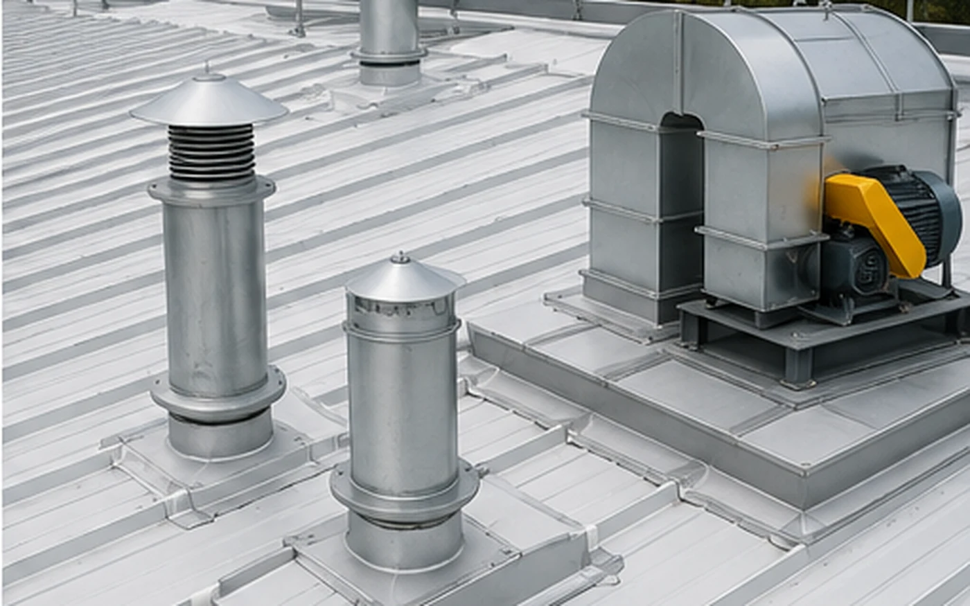
Roof penetrations may involve exhaust ducts, ventilation, piping, cable routes, roof-mounted equipment and equipment curbs. These should be coordinated with roof panels, purlins, roof framing, flashing, drainage and maintenance access.
Roof penetrations can affect roof drainage and weather performance. The interface between penetrations and the roof system should be reviewed before fabrication. This page does not provide universal curb or flashing details or guarantee watertightness. Related water-path and gutter interfaces are covered in steel building roof drainage planning.
Electrical and Cable-Route Interfaces
Cable trays, conduits, electrical equipment interfaces, wall and roof penetrations, and equipment connection areas should be reviewed during building coordination. However, Bingfa does not automatically provide electrical system design, cable sizing, circuit design or electrical load engineering. Bingfa’s scope is limited to coordinating the steel building openings and structural interfaces based on confirmed project information from the relevant specialists.
Compressed Air, Utility Piping and Process-Pipe Interfaces
Compressed-air lines, water and utility lines where applicable, process piping and equipment utility connections may affect penetrations, supports, equipment zones, maintenance access and enclosure details. Detailed process piping engineering is not part of Bingfa’s default scope. The steel building should be coordinated around confirmed utility and process-pipe information provided by the project specialists.
Ventilation, Exhaust and HVAC Penetrations
Duct routes, exhaust openings and ventilation equipment may affect wall openings, roof penetrations, secondary framing, roof drainage and maintenance. Detailed ventilation and HVAC sizing should be provided by the relevant specialists. This page focuses on the steel-building interface for ducts and ventilation equipment, not on system design. Operational airflow requirements are addressed separately in steel warehouse ventilation design.
Penetrations, Bracing and Secondary Steel
Service openings should be reviewed for potential conflicts with bracing, purlins, girts and structural members. If a service route conflicts with structural elements, the route, opening, secondary framing or structural arrangement may require project-specific review. This page does not provide reinforcement design guidance.
Review Your Service Penetration Requirements
If equipment locations, MEP drawings or approximate duct, pipe and cable routes are already available, these interfaces can be reviewed together before steel framing and enclosure details are finalized.
Discuss Your Project RequirementsEnclosure, Flashing and Weather Interfaces
Service penetrations through the roof or wall require coordination with panel continuity, trims, flashings, seals, water path and exterior exposure. Weather-interface detailing should be reviewed based on the specific penetration type and location. Final weather performance depends on the specific details and installation quality.
Fire, Smoke and Life-Safety Boundaries
Some penetrations may involve fire-rated assemblies, smoke control, fire stopping and sprinkler or life-safety systems. Where fire stopping or penetration sealing is required in fire-rated assemblies, it should be designed by the appropriate fire-protection specialists in accordance with the project requirements. Fire stopping and fire-stop system design are not part of the default steel building scope. Buyers should confirm fire-protection and life-safety requirements with the relevant project specialists. Bingfa does not automatically provide fire engineering, sprinkler design or local approval.
Maintenance Access Around Service Routes
Ducts, pipes, cable trays and equipment should not only be considered for installation. The route should also allow for inspection, maintenance, access panels, removal and future service access. Maintenance access should be reviewed alongside service route planning. Related clearance and inspection considerations are covered in steel building maintenance access.
Future Utility Changes and Additional Penetrations
Projects may later add equipment, add ducts, change piping, add cable routes, add ventilation or change service zones. Where known future changes are identified, initial planning can consider future interface areas, access, structural constraints and enclosure zones. However, future modifications should not be assumed to always be possible without engineering review. Any later structural modifications remain subject to engineering review. Broader extension considerations are covered in steel building future expansion planning.
Information to Confirm Before Steel Building Drawings Are Finalized
Before finalizing steel building drawings, the following information should be reviewed:
- Project use and operational requirements
- Equipment layout
- Known utility systems
- Service route drawings if available
- Wall penetration locations
- Roof penetration locations
- Opening dimensions where known
- Equipment loads and supports where relevant
- Duct, piping and cable tray routes
- Roof-mounted equipment
- Maintenance access
- Fire and life-safety information from specialists
- Future services if known
- Available MEP drawings
The more information available, the more accurately the building can be coordinated around confirmed service routes.
Service Penetration Coordination Checklist
| Item | Project / Specialist Information | Steel Building Coordination Point |
|---|---|---|
| Ducts | Route, size, location of duct openings | Wall/roof penetrations, secondary steel, enclosure interfaces |
| Pipes | Route, size, location of pipe penetrations | Wall/roof penetrations, secondary steel, enclosure interfaces |
| Cable Routes | Cable tray route, support locations | Structural clearance, support coordination, openings |
| Wall Openings | Location, size, required trim/sealing | Girts, secondary framing, panel coordination |
| Roof Openings | Location, size, curb details | Purlin and roof-framing interfaces, enclosure detailing and drainage coordination |
| Roof Equipment | Equipment location, size, support | Confirmed equipment load and location interfaces, roof penetrations and maintenance access |
| Bracing | Bracing location relative to service routes | Route coordination, potential conflicts |
| Secondary Steel | Purlin and girt locations | Penetration coordination, framing modifications |
| Envelope | Panel type, insulation, flashing | Weather detailing, trim, sealing |
| Drainage | Roof slope, gutter, downpipe locations | Penetration impact on drainage paths |
| Maintenance Access | Access requirements for service routes | Clearance, access panels, equipment access |
| Future Changes | Expected future services or equipment | Future interface planning, structural constraints |
How Bingfa Coordinates Service Penetrations With Steel Buildings
Bingfa coordinates service penetrations with steel buildings based on confirmed project information. Depending on the agreed scope, Bingfa may support review of confirmed service-opening information, structural-grid coordination, opening coordination, secondary framing interfaces, roof and wall enclosure interfaces, fabrication drawings, steel fabrication, quality checks, component identification and export packing.
Bingfa does not automatically provide MEP engineering, electrical design, HVAC engineering, process piping engineering, compressed-air system design, fire and sprinkler engineering, fire-stop design or local approvals. These should be provided by the relevant project specialists unless separately agreed.
Request a Steel Building Coordination Review
Send your building layout, equipment information, available MEP drawings and known wall or roof service openings. Our team can review the confirmed steel-building interfaces for your project.
Request a Project ReviewFrequently Asked Questions
1. What is a service penetration in a steel building?
A service penetration is an opening or interface location in the building envelope and coordinated framing zones that allows utilities and building services to pass through or connect with the building. Common examples include ducts, pipes, cable trays, electrical conduits, ventilation openings and equipment connections. Service penetrations should be coordinated before fabrication.
2. Should duct and pipe openings be confirmed before steel fabrication?
Where known, duct and pipe openings should be coordinated before fabrication so the structural layout, secondary framing and enclosure details can be reviewed around the required service routes. Late changes may require additional coordination and may affect fabrication or enclosure details.
3. Can service penetrations pass through steel columns, rafters or bracing?
Not without engineering review. Openings or modifications that affect structural members require engineering evaluation. Service routes should be coordinated to avoid conflicts with primary structural elements where practical. This page does not provide guidance on cutting or modifying structural steel.
4. How should roof penetrations be coordinated with steel roof panels?
Roof penetrations should be coordinated with roof panel layout, purlin spacing, roof framing, flashing and drainage. Penetrations can affect panel continuity and water-shedding paths. Weather detailing should be reviewed based on the specific penetration type and location.
5. What information should MEP or equipment suppliers provide to the steel building supplier?
MEP and equipment suppliers should provide service type, approximate route, opening location and dimensions where known, equipment location and loads where relevant, support requirements where applicable, and any available drawings. The more information available, the more accurately the building can be planned.
6. Does Bingfa design electrical, HVAC or process piping systems?
Bingfa’s core scope is the steel building and confirmed structural and enclosure interfaces. Detailed MEP and specialist system design should be provided by the relevant project specialists unless separately agreed. Bingfa may coordinate building openings and structural interfaces based on confirmed specialist information.