
STEEL BUILDING PLANNING GUIDE
Large Equipment Installation and Replacement Route Checklist for Steel Buildings
Check how large equipment will move from the delivery point through the building opening and internal route to its final position—and whether it can later be removed or replaced.
Quick Answer
Large-equipment access should be checked as one continuous route, starting outside the building and ending at the final equipment position. Future removal and replacement should also be considered before structural framing and fabrication are finalised.
Equipment transport dimensions may differ from installed dimensions, and doors, columns, bracing, walls and vertical obstructions can interrupt the route. There is no universal installation route for every project—the specific equipment, building layout and site conditions determine what is practical.
Why the Equipment Route Should Be Checked Before Steel Fabrication
Once the structural grid, bracing, permanent walls and openings are finalised, changing the equipment route may require project changes.
Early verification helps coordinate:
- Building openings
- Structural framing
- Equipment position
- Temporary access interfaces
- Future replacement access
Changes to steel framing, columns, bracing, walls or openings after fabrication can require additional redesign, fabrication or site coordination. Checking the equipment route earlier helps identify potential conflicts before the structural layout is finalised.
Buyers should therefore verify the equipment path before approving the steel building drawings.
For broader buyer planning, review the steel building procurement process before drawings and fabrication information are confirmed.
Start With the Equipment in Its Transport Condition
The operating dimensions are not always the dimensions used during delivery and installation.
Buyers should confirm where available:
- Equipment length, width and height in transport condition
- Transport orientation and configuration
- Equipment weight where relevant
- Removable components that reduce transport dimensions
- Folded, opened or dismantled condition during transport
- Lifting points provided by the equipment supplier where relevant
- Centre-of-gravity information where relevant to the installation specialist
The route should be checked using the equipment’s transport and installation condition, not only its final operating size.
Step 1: Check the Exterior Delivery Point
The route begins at the site entrance, unloading area or another confirmed exterior delivery point.
Buyers should verify that the equipment can reach the building before focusing only on the building opening.
Key checks include:
- Site entrance and approach for delivery vehicles
- Unloading or staging area
- Approach path to the building
- Fixed external obstacles
- Available project access and ground conditions
- Delivery vehicle access and manoeuvring requirements
External site constraints can affect equipment access even when the building opening itself is suitable.
This section does not provide road design, transport engineering or temporary-access engineering. Those requirements should be confirmed by the relevant project specialists where applicable.
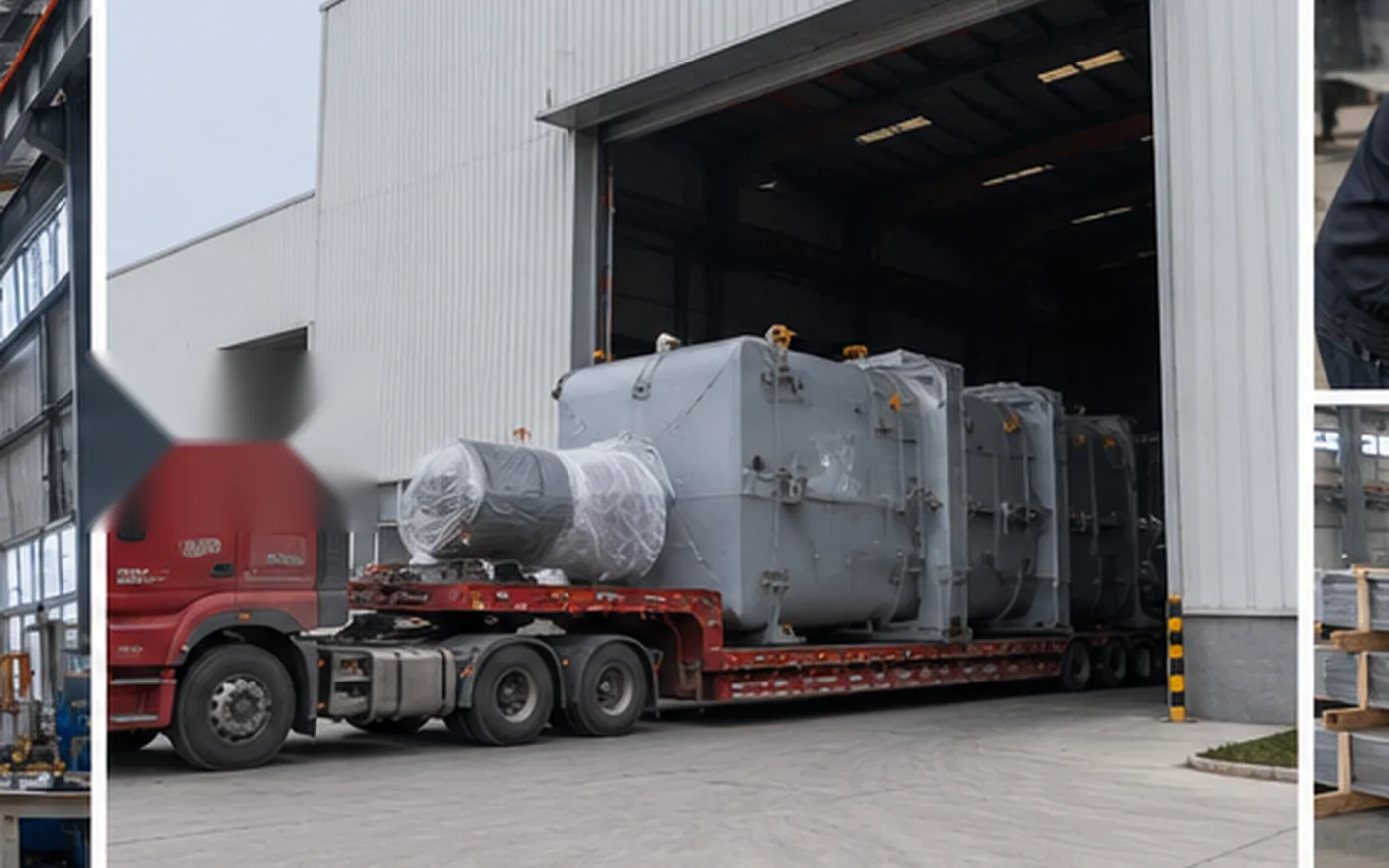
Step 2: Check the Building Opening
The building opening should accommodate the equipment in its confirmed transport or installation condition.
The opening is not only the nominal door size. Buyers should check the actual clear path through the building envelope.
Relevant items may include:
- Clear width
- Clear height
- Door frame
- Door hardware
- Thresholds
- Adjacent wall panels
- Nearby columns
- Bracing near the opening
- Other permanent obstructions
For detailed opening planning, buyers can review the steel warehouse door size guide.
No universal door width or height applies to every equipment-installation route.
Step 3: Check the Internal Movement Route
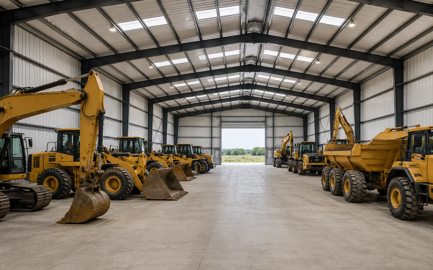
The internal movement route begins after the equipment passes through the building envelope and continues to its final location.
The entire path should be checked for fixed obstacles and usable movement space.
Relevant items may include:
- Available floor route
- Column locations
- Bracing members
- Permanent walls and partitions
- Existing machinery
- Equipment foundations or pits where relevant
- Mezzanine supports
- Fixed services
- Structural supports
- Access through different building zones
The internal route should be checked using the equipment’s transport condition and movement envelope.
A floor plan that appears open may still contain structural or permanent obstacles that affect equipment movement.
Step 4: Check Turning and Orientation Changes
Large equipment may not travel through the building in one straight line.
Depending on the equipment and route, movement may involve:
- Straight entry
- Reversing
- Turning
- Rotation
- Temporary orientation changes
- Movement in a different orientation from the final operating position
The equipment footprint alone is therefore not enough.
The full movement envelope matters.
Turning and orientation requirements should be checked at every point where the route changes direction. Required manoeuvring space depends on the specific equipment, handling method and installation plan.
This article does not provide universal turning-radius formulas or transport-engineering calculations.
Step 5: Check Vertical Clearance Along the Route
Vertical clearance should also be checked along the complete movement path.
Possible constraints may include:
- Structural frame geometry
- Frame haunches
- Lighting
- Ducts or building services
- Crane components where relevant
- Other permanent overhead obstructions
The required vertical space should follow the actual equipment transport and installation condition.
Where ducts, pipes or cable routes require dedicated openings along the installation path, related steel building service penetrations should be coordinated before fabrication.
For detailed vertical-clearance verification, buyers can review the steel building clear height guide.
Step 6: Check Columns and Bracing
Columns and bracing can interrupt an equipment route even when the overall floor area appears sufficient.
Possible route constraints include:
- Column lines
- Diagonal bracing
- Local structural connections
- Permanent wall framing
- Structural supports
- Narrow transitions between building zones
These interfaces should be reviewed before the structural framing is finalised.
For broader coordination of equipment zones, aisles and structural elements, the steel workshop layout guide provides additional context.
Where internal columns themselves become a primary constraint on the required horizontal working area, the large span industrial steel building solution may also be relevant.
Step 7: Check the Final Equipment Position
Reaching the final equipment position is only the last step of the movement route.
The final location should also support the equipment’s intended operation and future access requirements.
Buyers may need to confirm:
- Operating envelope
- Maintenance access
- Utility interfaces
- Adjacent equipment
- Working clearance
- Future service access
- Component-removal space
- Future equipment removal or replacement route
The final position should be coordinated with the building layout before structural framing and permanent building elements are finalised.
After the equipment is installed, buyers should also review routine maintenance access planning so service panels, aisles and clearances remain usable during operation.
This article does not provide machinery-layout or process-engineering services.
Check Your Equipment Installation Route
Installation Route vs Normal Operating Route
The equipment installation route may be different from the building’s normal daily circulation route.
An installation route may be used:
- Once during initial installation
- Occasionally during major servicing
- During later equipment replacement
- Only when large components need to enter or leave
The entire building does not necessarily need to be permanently organised around a temporary installation path if another project-specific solution is available.
The important point is that the required route and any temporary interfaces should be identified before the building design is finalised.
Temporary Openings and Removable Building Elements
Some projects may consider planned access provisions such as:
- Removable wall panels
- Planned access panels
- Temporary enclosure openings
- Future removable enclosure zones
These options must be treated carefully.
Structural members should never be assumed to be removable simply because they obstruct equipment access.
Any temporary opening, removable structural arrangement or future access provision that affects the structural system must be specifically reviewed and engineered for the project.
Bingfa may coordinate steel-building interfaces where they are included in the confirmed project scope, but structural changes should not be treated as simple site modifications.
When Temporary Lifting Is Required
Some large-equipment installations may involve:
- Mobile lifting equipment
- An existing overhead crane
- Temporary lifting equipment
- Other project-specific handling methods
The equipment-installation route should account for any confirmed lifting interfaces that affect the building opening, structural layout or available clearance.
Detailed lifting plans, rigging calculations, crane operating plans and temporary-works engineering are outside the scope of this article.
Where an industrial building permanently requires several overhead cranes and separate crane operating zones, buyers can review the industrial building with multiple overhead cranes solution.
When High Vertical Clearance Is Part of the Route
Some large equipment may require additional vertical space during:
- Entry
- Tilting
- Lifting
- Installation
- Removal
- Replacement
This can make vertical clearance a major building requirement rather than only a local access issue.
Projects where unusually high usable vertical space is a primary operational constraint can also be reviewed through the high-clearance industrial steel building solution.
When Internal Columns Become a Route Constraint
Internal columns can influence:
- Straight equipment access
- Turning
- Rotation
- Temporary staging
- Final positioning
- Future replacement
A route that appears wide enough overall may still be interrupted by the structural grid.
The structural layout should therefore be checked against the confirmed equipment route before fabrication information is finalised.
Where unobstructed horizontal space becomes a primary structural requirement, a large-span solution may need to be evaluated as part of the overall project design.
Future Equipment Replacement Route
Future equipment replacement is one of the most important route-planning issues because the original installation path may not remain available throughout the building’s service life.
Equipment may later require:
- Removal
- Replacement
- Major servicing
- Upgraded machinery
- Larger components
- A different installation method
The building itself may also change after initial construction.
Later changes can include:
- Additional machinery
- Permanent partitions
- Building services
- Storage systems
- New walls
- Structural modifications
- Different lifting arrangements
- Changed operational zones
The original installation route should therefore not automatically be assumed to remain available later.
Where future removal or replacement is reasonably foreseeable, it is useful to review the replacement route during the original building-planning stage.
When Future Equipment May Be Different
Future replacement equipment may not have the same characteristics as the original machine.
It may differ in:
- Length
- Width
- Height
- Weight
- Transport orientation
- Operating envelope
- Maintenance requirements
- Installation method
Future flexibility is not unlimited, and no steel building can be assumed to accommodate every possible future machine without review.
Where broader future physical building changes are already expected, the project can also be coordinated with steel building future expansion planning.
Equipment Installation Access in Warehouses
Warehouses may contain equipment such as:
- Automated storage equipment
- Material-handling systems
- Industrial machinery
- Large storage equipment
- Special handling systems
Equipment access should be coordinated with the warehouse opening, internal route and final operating zone.
For broader warehouse-building procurement, buyers can review steel warehouse buildings.
Detailed opening dimensions remain a separate door-planning issue rather than the main intent of this article.
Equipment Installation Access in Workshops and Factories
Workshops and factories may need installation or replacement routes for:
- Production machinery
- Assembly equipment
- Processing equipment
- Large industrial systems
- Replacement equipment
- Major maintenance components
The route should be coordinated with production zones, structural framing and future access.
For broader industrial-building procurement, buyers can review the industrial steel factory building page.
This article remains focused on route verification rather than full factory or workshop layout design.
What Information Should Buyers Provide Before Quotation?
Useful information for an initial steel building equipment installation route review includes:
- Project location
- Building use
- Equipment type
- Installed equipment dimensions
- Transport and installation dimensions
- Equipment weight where relevant
- Transport orientation
- Removable components if known
- Delivery vehicle information
- Required building opening if already defined
- Proposed internal movement route
- Turning or orientation requirements
- Final equipment position
- Maintenance access
- Future replacement requirements
- Layout drawing if available
- Equipment drawing if available
- Site plan if available
- Crane or lifting information if already defined
- Requested steel-building supply scope
- Delivery destination where relevant
Complete drawings are not mandatory for an initial review.
An initial discussion can begin with the available equipment and project information, and additional route requirements can be confirmed as the project develops.
Equipment Route Checklist Before Approving Steel Building Drawings
Before approving the steel building drawings, buyers should ask:
- Can the equipment reach the building from the exterior delivery point?
- Can it pass through the building opening?
- Can it move between structural columns?
- Does bracing interfere with the route?
- Can it turn or rotate where required?
- Is vertical clearance sufficient along the entire route?
- Can the equipment reach its final position?
- Is operating and maintenance access available?
- Can it later be removed?
- Has future equipment replacement been considered?
- Are temporary access requirements clearly documented?
- Have the relevant equipment or installation specialists confirmed their required interfaces where applicable?
The purpose of this checklist is to identify building-interface conflicts before the structural layout and fabrication information are finalised.
Discuss Your Steel Building Requirements
Frequently Asked Questions
1. Why should equipment installation routes be checked before steel fabrication?
Checking the route before fabrication allows openings, structural framing, columns, bracing and equipment zones to be coordinated before the building configuration is finalised. Changes after fabrication may require additional structural review, fabrication or site work, so early route verification can help identify conflicts sooner.
2. Is the equipment operating size enough to determine the installation route?
Not always. Equipment may have different dimensions or orientations during delivery and installation. Removable components, packaging, folded positions and temporary orientation changes can affect the required route. Buyers should verify the transport and installation condition in addition to the final operating dimensions.
3. Should the replacement route be planned at the same time as the installation route?
Where future removal or replacement is reasonably foreseeable, it is useful to review the replacement route together with the original installation route. Later access may be affected by new equipment, walls, building services or operational changes, so the original installation route should not automatically be assumed to remain available.
4. Can wall panels be removed later to replace large equipment?
Possibly, where removable panels or future access provisions are intentionally planned. However, the enclosure and structural interfaces must be reviewed for the specific project. Structural members cannot simply be removed without engineering review.
5. What if columns or bracing block the equipment route?
The route may need to change, or the structural layout may need to be reviewed before it is finalised. Relocating columns or bracing can affect the structural system and therefore requires engineering review rather than being treated as a simple site adjustment.
6. What equipment information should I provide before requesting a steel building quotation?
Provide the equipment type, installed dimensions, transport and installation dimensions, equipment weight where relevant, transport orientation, delivery vehicle information, required building opening if known, proposed internal route, turning or orientation requirements, final equipment position, maintenance access, future replacement requirements and any available equipment or layout drawings. An initial review can begin with the information currently available.