
STEEL WAREHOUSE STRUCTURAL GUIDE
Steel Warehouse Bracing Design:
Roof, Wall and Opening Coordination
Coordinate roof bracing, wall bracing, door openings, loading areas and future expansion before the warehouse structural layout is finalized.
Quick Answer
Steel warehouse bracing connects building stability with practical warehouse planning. Roof and wall bracing should be coordinated with doors, loading zones, equipment routes and future expansion before the structural layout is finalized. The final arrangement depends on the structural system, project loads, building geometry, openings, applicable design requirements and structural calculation. Removing, relocating or interrupting a designed brace requires structural review of the complete load path.
Introduction
When planning a steel warehouse, buyers often focus on span, height, column spacing and roof slope. Bracing may receive attention only after it conflicts with a loading door, forklift route or equipment opening.
Bracing is not a detail to solve after the layout is drawn. Its location affects door placement, equipment movement, loading access and future expansion, so buyers should confirm these inputs before the structural layout is finalized.
Early coordination also helps keep fabrication drawings, door schedules and erection planning aligned before material orders are locked.
What Is Steel Warehouse Bracing?
Steel warehouse bracing is part of the structural stability system. Main frames, bracing members, secondary steelwork and connections work together to transfer project actions through the building toward the supporting structure and foundations.
Common stability components may include roof bracing, wall bracing, braced bays and engineered connections. Diagonal bracing is common, but the required system depends on the structural concept, geometry, project loads, openings and governing design requirements.
How Bracing Fits into the Warehouse Load Path
Bracing is one part of the load path: the route by which forces move through the designed structural system toward the supports and foundations. Project design loads should be reviewed before the bracing layout is fixed.
For planning, horizontal actions may pass through the roof and wall stability system, secondary framing or bracing system as applicable, into the main structure and then toward columns, bases and foundations. The exact route should be confirmed by the project engineer.
Roof Bracing vs. Wall Bracing
Roof bracing and wall bracing perform different but connected roles in the designed stability system.
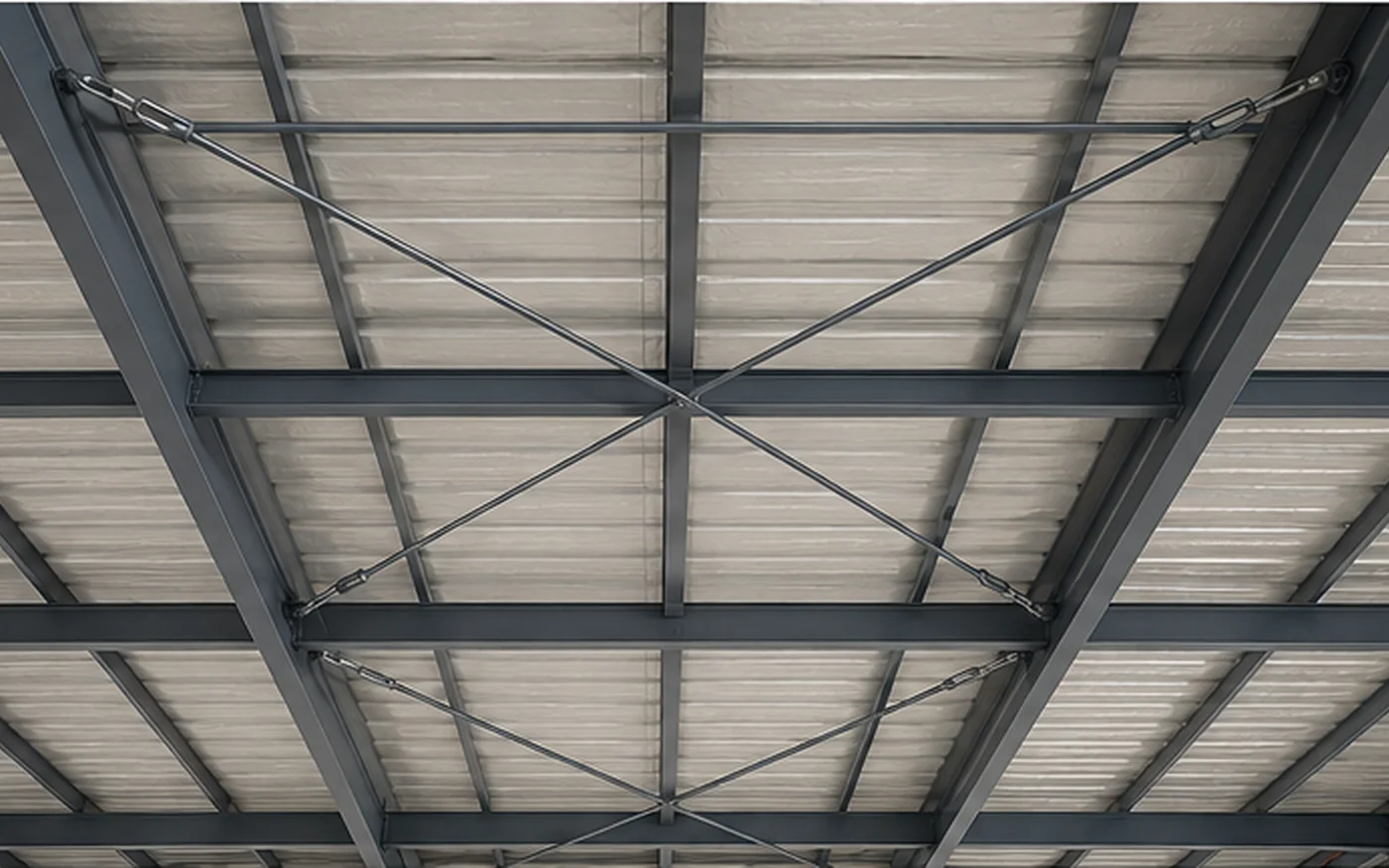
| Area | Role in the Structural System | What the Buyer Should Check |
|---|---|---|
| Roof Bracing | Forms part of the designed roof-plane stability system and helps transfer longitudinal or horizontal actions toward the main stability elements, depending on the structural scheme. | Are there roof openings, roof-mounted systems or planned future roof works that may conflict with the proposed bracing zone? |
| Wall Bracing | Forms part of the vertical stability system and transfers designed forces toward the supporting structure and foundations. | Are doors, windows or other wall openings planned in the same bay? |
| Braced Bay | A bay selected as part of the engineered stability arrangement. | Does the bay also need a loading door, personnel door, roller shutter or large opening? |
| Opening Area | Doors, windows, service openings or equipment access points in the building envelope. | Has each opening location been checked against the proposed bracing layout? |
| Future Expansion Area | An area that may later receive additional bays, openings or building extension. | Has the future expansion plan been identified before the initial stability layout is finalized? |
Use the table to identify coordination items before drawings are approved.
What Is a Braced Bay?
A braced bay is selected as part of the building’s engineered stability system. Its location must work with the structural scheme, project loads, geometry, openings and operational requirements.
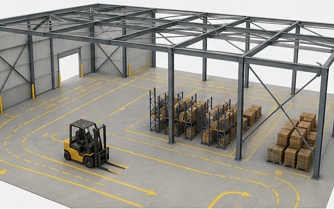
A bay that looks convenient for bracing may also be needed for a loading door, equipment access or future expansion. If these requirements are communicated late, the structural layout may need review before fabrication or erection.
How Bracing Location Affects Doors and Openings
Door and opening conflicts are one of the most practical reasons to coordinate bracing early. Door quantity, door size and door position should be reviewed with the braced-bay layout.
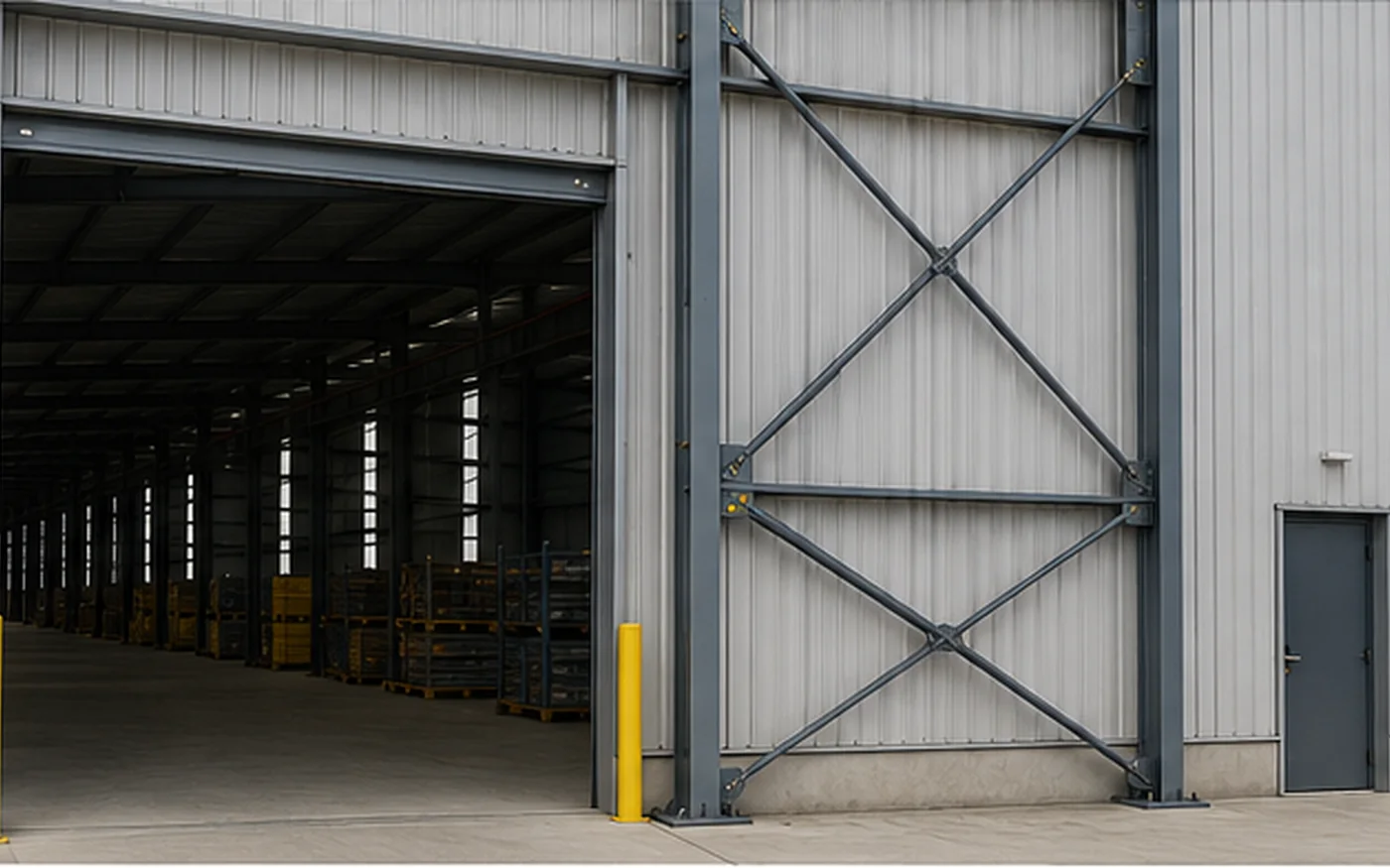
A planned braced bay may also be required for a loading door, roller shutter, personnel door, service opening or equipment opening. If those functions overlap, the project team should resolve the conflict before the structural layout is finalized.
Possible responses include relocating the opening, reviewing another bracing location, evaluating an alternative stability arrangement or adjusting the wider layout. None should be treated as automatic.
Bracing and Warehouse Operational Layout
Bracing can affect daily warehouse use as well as the envelope. Wall bracing should be coordinated with forklift paths, vehicle circulation, loading zones, rack layouts, equipment access, maintenance routes and any connected workshop function.
The goal is not to move bracing whenever a conflict appears, but to identify operating requirements early enough for coordinated structural review.
How Bracing Coordinates with the Structural System
Coordination with Purlins, Girts and Main Frames
Roof bracing must be coordinated with rafters, purlins and the designed roof stability system. Wall bracing must be coordinated with columns, wall secondary steelwork and the designed vertical stability system.
Connections, force transfer and member roles depend on the structural design. Purlins, girts and main-frame members should not be assumed to perform a stability function unless that role is engineered. Buyers should provide final openings and operating layout before detailed steel coordination.
Foundation Reactions
Forces carried by the stability system must transfer through the supporting structure and into the foundations. A revised bracing arrangement may affect columns, base connections, anchor arrangements or foundation reactions.
This guide does not size foundations, anchor bolts or connections. Those items require project-specific structural design. For construction coordination, refer to the steel building foundation and anchor bolt checklist.
Future Expansion and Changes After Structural Design
Planning for Future Expansion
Future expansion should be identified during the original design stage whenever it is reasonably expected. Overall warehouse size, expansion direction, new loading doors, equipment openings and changed circulation should be considered together.
Early planning does not guarantee expansion without later structural modification, but it lets the design team evaluate the requirement before the first-stage stability system is finalized.
Changing Bracing After Design
Moving or modifying bracing can affect adjacent members, connections, other braced bays, column bases and foundations. If a change is required after design, the project team should review the revised load path, affected members, connections, foundations and drawings before implementation.
Common Steel Warehouse Bracing Planning Mistakes
- Confirming doors after the bracing layout is finalized. Late loading-door or roller-shutter changes may conflict directly with a braced bay and trigger structural redesign.
- Assuming a brace can simply be removed. A designed brace forms part of a stability system. Removing it requires structural review of the alternative load path.
- Copying another project’s bracing arrangement. Building geometry, loads, openings, structural systems and operational requirements vary from project to project.
- Ignoring future expansion. A future extension, loading door or equipment opening may conflict with the initial stability arrangement if the plan is not identified early.
- Ignoring equipment and vehicle routes. Operational circulation should be checked against wall bracing and other stability elements before layout approval.
- Treating roof and wall stability systems independently. The final stability system must be coordinated as a whole.
- Changing openings without structural review. A new opening can interrupt a designed bracing zone or alter the assumptions used in the structural layout.
Steel Warehouse Bracing Input Checklist
| Information | What to Provide | Why It Matters |
|---|---|---|
| Project location | Country / region | Helps establish the applicable project environment and design requirements. |
| Building dimensions | Length × width × eave height | Defines the overall geometry used for structural planning. |
| Building use | Storage, distribution, manufacturing, etc. | Helps identify operational requirements and opening locations. |
| Structural system if known | Portal frame, truss, rigid-frame arrangement, etc. | Helps the design team understand the intended structural concept. |
| Door locations | Position, size and type | Braced bays and door locations must be coordinated. |
| Large openings | Equipment access, conveyor openings, service openings, etc. | Large openings may conflict with proposed stability zones. |
| Loading bays | Number and position | Proposed loading bays should be checked against braced-bay locations before the structural layout is finalized. |
| Rack layout | Planned rack positions | Wall-side rack layout and operating clearance may need coordination with wall bracing locations. |
| Equipment routes | Forklift, vehicle and maintenance routes | Helps identify operating areas that should be reviewed against the structural layout. |
| Crane if applicable | Capacity, span, hook height and available crane data | Crane requirements may affect the overall structural design and stability review. |
| Future expansion | Additional bays, future openings or extension direction | Allows the initial stability arrangement to be reviewed with future plans in mind. |
| Local design requirements | Known code, client or project requirements | Must be considered by the project design team. |
| Drawings if available | Preliminary layout, architectural plans or equipment arrangement | Provides the clearest basis for early coordination. |
Providing this information early reduces avoidable conflicts between structural stability and warehouse operation.
Need Help Coordinating Your Warehouse Layout?
Share building dimensions, planned doors, loading areas and future expansion requirements before the structural layout is finalized.
FAQ
What is the purpose of bracing in a steel warehouse?
Bracing forms part of the designed building stability system. Depending on the structural scheme, it may help transfer horizontal actions through the structure toward the supporting elements and foundations.
What is the difference between roof bracing and wall bracing?
Roof bracing is coordinated within the roof-plane stability system, while wall bracing forms part of the vertical stability system. Their exact roles and connections depend on the engineered structural arrangement.
Can a warehouse door be placed in a braced bay?
Possibly, but the opening and bracing arrangement must be coordinated structurally. A brace should not simply be removed to make space for a door.
Can steel warehouse bracing be moved after design?
Possible changes require structural review because relocating bracing may affect the load path, adjacent members, connections, other stability elements and foundations.
Does every steel warehouse use X bracing?
No. X-bracing is one possible arrangement, but it is not universal. Depending on the structural system and project requirements, longitudinal stability may use alternative bracing arrangements, portalised bays or other engineered stability systems.
What information is needed before the bracing layout is confirmed?
Provide the building dimensions, project location, door and opening locations, loading areas, rack or equipment layout, future expansion requirements and available drawings before the structural layout is finalized.
Planning a Steel Warehouse Project?
Submit project location, dimensions, openings, operational layout and available drawings for an initial review.